An Insight into Practical Heat Exchanger Sizing and Design
Heat exchangers are indispensable in chemical, petroleum, food processing, pharmaceutical, power generation, and HVAC industries because they enable the efficient transfer of heat from one fluid to another without direct mixing. Whether heating, cooling, condensing, or vaporizing process streams, their performance has a significant impact on plant efficiency, energy consumption, operating costs, and product quality.
The effectiveness of a heat exchanger depends largely on proper sizing. An undersized unit may fail to meet the required process temperatures, reducing production efficiency and increasing energy demand. Conversely, an oversized exchanger raises capital costs, occupies unnecessary plant space, and may result in poor flow distribution or excessive pressure losses. Consequently, heat exchanger sizing is a critical engineering task that integrates principles of thermodynamics, heat transfer, fluid mechanics, material science, and economic analysis.
This article presents a systematic approach to heat exchanger sizing, introducing the fundamental design equations, the key engineering considerations, and a worked example that illustrates the complete sizing procedure.
Understanding Heat Exchanger Sizing
Heat exchanger sizing is the engineering process of determining the dimensions and thermal characteristics required to transfer a specified amount of heat between two process streams under given operating conditions.
Rather than simply calculating the required heat transfer area, the design process aims to determine the optimum equipment configuration that satisfies both thermal and hydraulic requirements. The final design specifies parameters such as the heat transfer surface area, shell diameter, tube dimensions, number of tubes, pressure drop, and overall heat transfer coefficient while ensuring reliable long-term operation.
Among the various exchanger configurations available, shell-and-tube heat exchangers remain the industry standard because of their ability to withstand high temperatures and pressures, accommodate a wide range of process fluids, and facilitate maintenance. Plate heat exchangers are preferred where compactness and high heat transfer rates are required, while double-pipe exchangers are generally reserved for smaller duties. Air-cooled heat exchangers become attractive in locations where cooling water is unavailable or expensive.
Click Here to Join the Over 10,000 Students Taking Highly Rated Courses in Manufacturing, Quality Assurance/Quality Control, Project Management, Engineering, Food Safety, Lean Six Sigma, Industrial Safety (HSE), Lean Manufacturing, Six Sigma, ISO 9001, ISO 14001, ISO 22000, ISO 45001, FSSC 22000, Product Development etc. on UDEMY.
Process Information Required Before Sizing
Successful heat exchanger design begins with accurate process data. The engineer must know the flow rates, inlet and outlet temperatures, operating pressures, specific heats, densities, viscosities, and thermal conductivities of both the hot and cold streams. Additional information such as fouling tendencies, allowable pressure drop, corrosion characteristics, and material compatibility is equally important because these factors strongly influence equipment selection and long-term performance.
Incomplete or inaccurate process data often leads to incorrect sizing, making this stage one of the most important aspects of exchanger design.
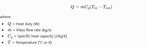
Step 1: Determining the Heat Duty
The first step is to calculate the amount of heat that must be transferred.
For sensible heating or cooling,
When condensation or vaporization occurs, latent heat must be considered instead:

Determining the heat duty establishes the thermal load that the exchanger must accommodate.
Click Here to Join the Over 10,000 Students Taking Highly Rated Courses in Manufacturing, Quality Assurance/Quality Control, Project Management, Engineering, Food Safety, Lean Six Sigma, Industrial Safety (HSE), Lean Manufacturing, Six Sigma, ISO 9001, ISO 14001, ISO 22000, ISO 45001, FSSC 22000, Product Development etc. on UDEMY.
Step 2: Selecting the Flow Arrangement
The arrangement of fluid flow has a major influence on exchanger performance. Counter-current flow is generally preferred because it maintains a larger average temperature difference throughout the exchanger, leading to higher thermal efficiency and a smaller required heat transfer area.
Parallel-flow exchangers are easier to construct but are less efficient because the temperature driving force decreases rapidly along the flow path. Cross-flow arrangements are widely used in air coolers and automotive radiators where one of the fluids is typically air.
Because of its superior thermal performance, counter-current flow is the preferred choice for most industrial process applications.
Step 3: Calculating the Log Mean Temperature Difference
Heat transfer is driven by the temperature difference between the hot and cold fluids. Since this temperature difference changes continuously along the exchanger, the Log Mean Temperature Difference (LMTD) provides an effective average value.

The LMTD is one of the most important parameters in thermal design because it represents the effective temperature driving force for heat transfer.
Step 4: Estimating the Overall Heat Transfer Coefficient
Heat must pass through several thermal resistances before reaching the cold fluid. These include convection on both fluid sides, conduction through the tube wall, and additional resistance caused by fouling deposits.
These combined effects are represented by the overall heat transfer coefficient, U, in the fundamental heat transfer equation:

Typical values of U vary considerably depending on the service. Gas-to-gas exchangers generally have low coefficients because gases possess poor thermal conductivity, whereas steam condensers may exhibit coefficients several thousand watts per square metre per kelvin due to the high heat transfer associated with phase change. Engineers typically estimate an initial value from design references before refining it during detailed design.
Click Here to Join the Over 10,000 Students Taking Highly Rated Courses in Manufacturing, Quality Assurance/Quality Control, Project Management, Engineering, Food Safety, Lean Six Sigma, Industrial Safety (HSE), Lean Manufacturing, Six Sigma, ISO 9001, ISO 14001, ISO 22000, ISO 45001, FSSC 22000, Product Development etc. on UDEMY.
Step 5: Calculating the Required Heat Transfer Area
Once the heat duty, LMTD, and overall heat transfer coefficient are known, the required heat transfer surface area can be determined from

This calculation provides the minimum heat transfer area necessary to satisfy the specified process conditions and serves as the basis for selecting tube dimensions and exchanger geometry.
Step 6: Selecting Tube Dimensions and Hydraulic Design
After determining the required area, the designer selects suitable tube diameters, lengths, and tube arrangements to provide the calculated surface area.The total external surface area is given by

where N is the number of tubes, D is the tube outside diameter, and L is the tube length.
Hydraulic performance must also be evaluated at this stage. Excessively low fluid velocities reduce heat transfer and encourage fouling, whereas very high velocities increase pressure losses and pumping costs. For most liquid services, tube-side velocities between 1 and 2 m/s provide a reasonable balance between thermal performance and pressure drop.
Pressure Drop and Fouling Considerations
A heat exchanger must satisfy not only thermal requirements but also hydraulic constraints. Excessive pressure drop increases pumping power and operating costs, while insufficient velocity can accelerate fouling and reduce thermal performance.
Fouling is an inevitable consequence of long-term operation, particularly when handling cooling water, crude oils, or process streams containing suspended solids. Deposits on heat transfer surfaces introduce additional thermal resistance, reducing the effective heat transfer coefficient. Consequently, appropriate fouling factors are incorporated during design to ensure that the exchanger continues to meet process requirements throughout its operating life.
Click Here to Join the Over 10,000 Students Taking Highly Rated Courses in Manufacturing, Quality Assurance/Quality Control, Project Management, Engineering, Food Safety, Lean Six Sigma, Industrial Safety (HSE), Lean Manufacturing, Six Sigma, ISO 9001, ISO 14001, ISO 22000, ISO 45001, FSSC 22000, Product Development etc. on UDEMY.
Mechanical Design Considerations
Thermal calculations alone do not produce a complete exchanger design. Mechanical integrity must also be verified to ensure safe operation under the intended pressure and temperature conditions.
The designer evaluates thermal expansion, tube vibration, shell stresses, tube sheet thickness, corrosion allowance, nozzle sizing, support structures, and applicable design codes. These considerations ensure that the exchanger remains reliable throughout its service life while meeting safety and regulatory requirements.
Modern Heat Exchanger Design Software
Although hand calculations provide the theoretical foundation for heat exchanger sizing, modern engineering design relies heavily on specialized simulation software. Programs such as DWSIM, Aspen HYSYS, Aspen EDR, Aspen Plus, CHEMCAD, HTRI Xchanger Suite, COMSOL Multiphysics, and ANSYS Fluent enable engineers to perform rigorous thermal analysis, hydraulic calculations, fouling evaluation, optimization, and mechanical verification with greater accuracy than manual methods alone.
Conclusion
Heat exchanger sizing is a multidisciplinary engineering exercise that extends far beyond calculating heat transfer area. A successful design integrates heat transfer theory, thermodynamics, fluid mechanics, materials engineering, hydraulic analysis, and economic considerations to produce equipment that is both technically effective and financially viable.
The design procedure begins by establishing the required heat duty, followed by selecting the most suitable flow arrangement, calculating the log mean temperature difference, estimating the overall heat transfer coefficient, and determining the required heat transfer area. The preliminary thermal design is then refined through hydraulic analysis, fouling assessment, and mechanical verification to ensure reliable long-term operation.
Ultimately, an accurately sized heat exchanger improves energy efficiency, reduces operating costs, minimizes maintenance requirements, and enhances overall plant productivity. As industries continue to prioritize energy conservation and sustainable process design, the ability to correctly size and optimize heat exchangers remains one of the most valuable skills for chemical and mechanical engineers.
Click Here to Join the Over 10,000 Students Taking Highly Rated Courses in Manufacturing, Quality Assurance/Quality Control, Project Management, Engineering, Food Safety, Lean Six Sigma, Industrial Safety (HSE), Lean Manufacturing, Six Sigma, ISO 9001, ISO 14001, ISO 22000, ISO 45001, FSSC 22000, Product Development etc. on UDEMY.