Electrical Systems in Process Plants (For All Disciplines in Engineering)
As I look back in time, I' am reminded of what a swaggering little fresh postgraduate chemical engineer I was, until I was left in the lurch due to a dearth of practical Industrial know-how. A few months into my job and I realized that, irrespective of one’s core qualification, it is necessary to grasp some knowledge of other ancillary disciplines because no one branch of engineering caters to all the industrial needs. For a start, it is imperative for chemical and mechanical engineers to arm themselves with some knowledge of electrical systems and machinery.
One of the day-in-day-out job of a chemical or mechanical design engineer in the engineering industry is to estimate the power requirements of an electrical motor. Although this might suffice with a an electrical engineer around to work out the remaining requirements, there is no harm, rather, beneficial for Engineers to go the extra mile in gaining experience in assessing and selecting electrical equipment.
 Click Here to Join the Over 3200 Students Taking our Highly Rated Courses on Quality Assurance/Quality Control, Project Management, Engineering, Food Safety, Lean Six Sigma, Industrial Safety (HSE), Lean Manufacturing, Six Sigma, ISO 9001, ISO 14001, ISO 22000, ISO 45001, FSSC 22000, Product Development etc. on UDEMY.
Drivers for Rotating Equipment
The two most common types of rotating equipment in the oil & gas industry are centrifugal compressors, centrifugal pumps. Although traditionally gas turbines have catered to running centrifugal compressors, Electrical Motors have also equally found their way into meeting demands as a prime mover. In locations where surplus power is available, electrical motors are a good alternative, offer much better efficiency than gas turbines and are a better bet due to lower maintenance headaches.
Click Here to Join the Over 3200 Students Taking our Highly Rated Courses on Quality Assurance/Quality Control, Project Management, Engineering, Food Safety, Lean Six Sigma, Industrial Safety (HSE), Lean Manufacturing, Six Sigma, ISO 9001, ISO 14001, ISO 22000, ISO 45001, FSSC 22000, Product Development etc. on UDEMY.
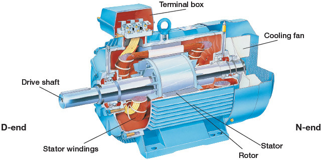
Asynchronous Induction Motor
Asynchronous Induction motors are popular in process industries partly due to their simple design, ruggedness and low maintenance. A 3-Phase asynchronous induction motor design consists of a rotor and a stator surrounded by copper coils which induces a magnetic field (hence the name induction) on the rotor causing the rotor to rotate. The chief parameters used to determine the speed of a given induction motor is the ‘AC current frequency’ and the 'number of poles' around which the copper coils is wound. Copper coils have high electrical conductivity and hence higher efficiency although sometimes aluminium is used because of its lightweight properties and is less expensive. Using these parameters, the synchronous speed of a motor (i.e., the speed at which the magnetic field rotates and acts on the rotor) is calculated as follows,

The term ‘Ns’ represents the synchronous speed (measured as revolutions per minute or ‘rpm’), ‘f’ represents the current frequency and 'P' represents the number of poles. In a 3-Phase Induction motor, three alternating current (AC) lines pass through that stator side with a phase difference of 120 degrees and produce a magnetic field.
Theoretically, if the magnetic field is produced to run at a certain speed (say 3000 rpm), the rotor should also rotate at the same speed. But practically, this would not be the case, since the rotor shaft is connected to a load. The rotor speed tends to lag behind in picking up the magnetic field’s rotational effects thereby causing the rotor to rotate at a slightly lower speed compared to the synchronous speed. This lag is known as ‘Slip’. Slip percentages are about 1% to 2% at full load but during startup can even reach 4% to 5%. Motors are also associated with the term ‘Torque’ which represents the turning effect of force.
Click Here to Join the Over 3200 Students Taking our Highly Rated Courses on Quality Assurance/Quality Control, Project Management, Engineering, Food Safety, Lean Six Sigma, Industrial Safety (HSE), Lean Manufacturing, Six Sigma, ISO 9001, ISO 14001, ISO 22000, ISO 45001, FSSC 22000, Product Development etc. on UDEMY.
An induction motor with a higher torque means higher capacity to overcome the inertia of a system and get it kick started from a state of rest.
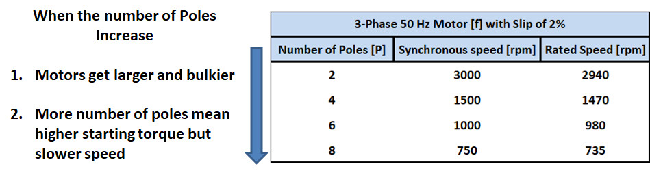
In simple terms, for a given power capacity of an asynchronous induction motor, with higher torque, you get less speed and vice versa. If higher speeds and torque is required, a higher powered motor is needed.
It must be remembered that a motor with higher number of poles are bulkier and are more expensive. Therefore a 2 pole or a 4 pole motor is preferred. Below is a table that summarizes the different synchronous speeds of a 3-phase, 50 Hz induction motor and what they imply.
Click Here to Join the Over 3200 Students Taking our Highly Rated Courses on Quality Assurance/Quality Control, Project Management, Engineering, Food Safety, Lean Six Sigma, Industrial Safety (HSE), Lean Manufacturing, Six Sigma, ISO 9001, ISO 14001, ISO 22000, ISO 45001, FSSC 22000, Product Development etc. on UDEMY.
Induction Motor Characteristics
Besides the mechanical construction, an asynchronous induction motor is characterized by ‘Speed vs. Torque’ Curves which is necessary to choose a motor for a given application. Below is an image that depicts a speed vs. torque curves and what they represent.
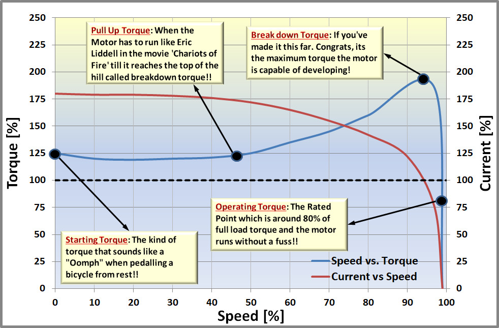
On a serious note, the following terminologies are employed to explain the various types of torque,
- Starting Torque: The amount of torque required to overcome the inertia of a standstill.
- Pull-Up Torque: The minimum torque generated by a motor as it accelerates from standstill to operating speed.
- Break Down Torque: The maximum torque that the motor is capable of developing.
- Full Load Torque: The torque required to produce the rated power of an electrical motor at full-load speed.
- Rated Torque: The maximum continuous torque available at the design speed that allows the motor to do the work without overheating.
- Full Load Speed: Synchronous Speed - Slip%
Click Here to Join the Over 3200 Students Taking our Highly Rated Courses on Quality Assurance/Quality Control, Project Management, Engineering, Food Safety, Lean Six Sigma, Industrial Safety (HSE), Lean Manufacturing, Six Sigma, ISO 9001, ISO 14001, ISO 22000, ISO 45001, FSSC 22000, Product Development etc. on UDEMY.
The image also depicts that
- When the motor starts up, the alternating current drawn through the stator side initially is very high and subsides only after crossing the breakdown torque.
- As the load on the motor increases, speed decreases while the current absorbed increases.
- In case the load increases to an exceptionally high value and the motor cannot overcome the system inertia to bring the compressor to running condition, it causes a deceleration of speed and subsequently increases the drawn-in current. With high drawn-in currents, the motor coils can be expected to overheat and turn into a cauldron of Spaghetti.
Click Here to Join the Over 3200 Students Taking our Highly Rated Courses on Quality Assurance/Quality Control, Project Management, Engineering, Food Safety, Lean Six Sigma, Industrial Safety (HSE), Lean Manufacturing, Six Sigma, ISO 9001, ISO 14001, ISO 22000, ISO 45001, FSSC 22000, Product Development etc. on UDEMY.
National Electrical Manufacturer’s Association (NEMA)
The National Electrical Manufacturer’s Association (NEMA) is an organization that sets the standards for manufacturing of electrical equipment. In the case of electrical induction motors, NEMA sets 4 types of Torque vs Speed Characteristics namely, NEMA A, NEMA B, NEMA C and NEMA D. The characteristics of the different types of NEMA curves are explained below.

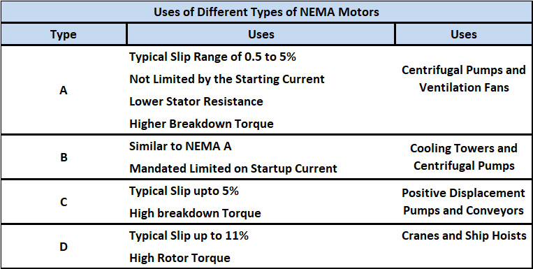
Among these, NEMA A and NEMA B are most commonly used due to their high breakdown characteristics and low slip (1% to 5%).
Click Here to Join the Over 3200 Students Taking our Highly Rated Courses on Quality Assurance/Quality Control, Project Management, Engineering, Food Safety, Lean Six Sigma, Industrial Safety (HSE), Lean Manufacturing, Six Sigma, ISO 9001, ISO 14001, ISO 22000, ISO 45001, FSSC 22000, Product Development etc. on UDEMY.
A Case Study: Induction Motor for an Air Compressor
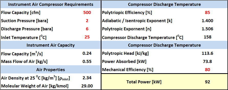
Imagine that you have to estimate the power requirements of an 500 ACFM (Actual cubic feet/min) Air Compressor that has to draw air from the ambient atmosphere at 25 deg.C at 2 bar(a) and compress it to 6 bar(a). To begin with, the following assumptions are made. The Torque vs. Speed Curves shown in the previous section can be taken as the motor characteristics for the computations.
Assumptions
- The compressor is assumed to run at its best polytropic efficiency point of 85% and a total mechanical efficiency of 80%.
- The pressures at which the compressor is operated is low and hence the compressibility factor (Z) and Cp/Cv of the gas is not expected to change much and Cp/Cv can taken to be 1.4.
- The Instrument air system has the necessary equipment to meet specifications stated in the ANSI/ISA 7.0.01 “Quality Standard for Instrument Air”.
Click Here to Join the Over 3200 Students Taking our Highly Rated Courses on Quality Assurance/Quality Control, Project Management, Engineering, Food Safety, Lean Six Sigma, Industrial Safety (HSE), Lean Manufacturing, Six Sigma, ISO 9001, ISO 14001, ISO 22000, ISO 45001, FSSC 22000, Product Development etc. on UDEMY.
What is the power requirement of the Air Compressor??
Calculation Steps
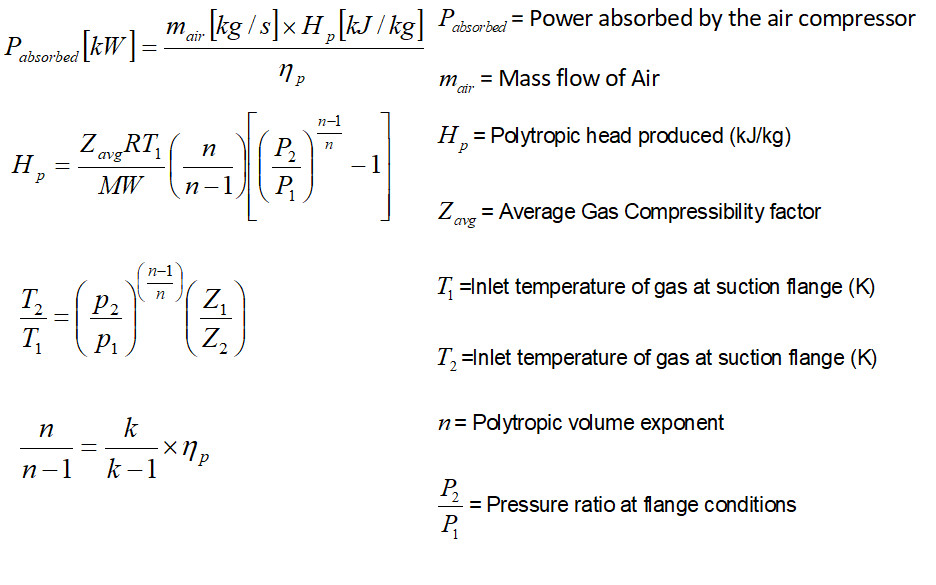
- Calculate the polytropic exponent using specific heat ratio [Cp/Cv =k] and polytropic exponent [n].
- Calculate the polytropic head [Hp] that needs to be developed by the air compressor i.e, how much energy is required to compress 1 kg of air from the initial condition of 2 bar(a) to 6 bar(a).
- Calculate the power requirements by multiplying the polytropic head [Hp] by the mass flow followed by taking into account the polytropic efficiency and mechanical efficiency.
Click Here to Join the Over 3200 Students Taking our Highly Rated Courses on Quality Assurance/Quality Control, Project Management, Engineering, Food Safety, Lean Six Sigma, Industrial Safety (HSE), Lean Manufacturing, Six Sigma, ISO 9001, ISO 14001, ISO 22000, ISO 45001, FSSC 22000, Product Development etc. on UDEMY.
The above steps are used in an MS-Excel Sheet and it is seen that the power required is about 92 kW (or ~124 HP).
 The torque and power are related by the basic equation as follows,

Based on the horsepower calculation in the above case study, if a 3-Phase, 50Hz, 4 pole squirrel cage induction motor is selected the torque required to sustain the compressor at rated conditions of 6 bar(a) and 500 ACFM during running conditions of the air compressor at a full load speed of 1470 rpm would be about,

The breakdown torque at 185% torque (ie., at 97% of full load speed) from the torque vs. Speed grpah in the previous section is calculated as,

Click Here to Join the Over 3200 Students Taking our Highly Rated Courses on Quality Assurance/Quality Control, Project Management, Engineering, Food Safety, Lean Six Sigma, Industrial Safety (HSE), Lean Manufacturing, Six Sigma, ISO 9001, ISO 14001, ISO 22000, ISO 45001, FSSC 22000, Product Development etc. on UDEMY.
Selection of Induction Motor Capacity
The ideal case of selecting the induction motor is to ensure that the operating point of the electric motor is between 80% to 85% of the motor's full load torque (i.e., 100% Torque line).
Based on the case study, as per NEMA standards for a 4 pole, 50 Hz, polyphase, squirrel cage induction motor, either a 125 HP (93 kW) motor or a 150 HP with a breakdown torque of 200% motor can be selected.
Choosing the 125 HP motor for the running case of 124 HP would mean that the motor is running in a neck to neck situation of 124 HP / 125 HP = ~99.2% of the motor's full load torque. Besides, the calculation made above does not take into account the compressor rotor and gas loads on the motor and therefore could cause the 125 HP motor to struggle to help reach the compressor's rated conditions of 6 bar(a).
Therefore it is more prudent to choose a 150 HP motor which offers a margin. In the case study made, the maximum torque that can be provided by the 150 HP induction electric motor at break down conditions is calculated at the breakdown torque’s corresponding speed. The breakdown torque at 200% for the selected 150 HP (~112 kW) motor (ie., at 97% of full load speed) is calculated as,

It is to be noted that although the breakdown torque is higher for a 150 HP induction motor, when the air compressor reaches the full load speed of 1470 rpm, the torque required would be at 124 HP / 150 HP, i.e., at ~83% of the full load torque (100% torque line) which satisfies the 80% to 85% of the full load torque condition.
Click Here to Join the Over 3200 Students Taking our Highly Rated Courses on Quality Assurance/Quality Control, Project Management, Engineering, Food Safety, Lean Six Sigma, Industrial Safety (HSE), Lean Manufacturing, Six Sigma, ISO 9001, ISO 14001, ISO 22000, ISO 45001, FSSC 22000, Product Development etc. on UDEMY.
Cautionary Note
Selecting an extremely powerful induction motor for a given compressor system can cause short startup times. This means the anti-surge valve also has to respond fast enough to recycle cold gas back to the compressor to avoid a high head at low flow situation, i.e., a surge during a compressor startup. Hence for the motor selected, a process dynamic simulation is always advisable to understand the induction motor's effect on the compressor behaviour and ensure that the right torque vs. speed curves and motor power have been selected.
References: [1], [2], [3], [4], [5], [6], [7], [8], [9], [10], [11], [12]
Click Here to Join the Over 3200 Students Taking our Highly Rated Courses on Quality Assurance/Quality Control, Project Management, Engineering, Food Safety, Lean Six Sigma, Industrial Safety (HSE), Lean Manufacturing, Six Sigma, ISO 9001, ISO 14001, ISO 22000, ISO 45001, FSSC 22000, Product Development etc. on UDEMY.
About the Author
Vijay Sarathy holds a Master’s Degree in Chemical Engineering from Birla Institute of Technology & Science (BITS), Pilani, India and is a Chartered Engineer from the Institution of Chemical Engineers, UK. His expertise over 16 years of professional experience covers Front End Engineering, Process Dynamic Simulation and Subsea/Onshore pipeline flow assurance in the Oil and Gas industry. Vijay has worked as an Upstream Process Engineer with major conglomerates of General Electric, ENI Saipem and Shell.
