Geometric Dimensioning & Tolerancing (GD&T) in Manufacturing
In manufacturing, quality is vital, costs needs to be controlled and the processes must be designed to minimize waste and use resources wisely. To reduce cost many component parts are currently being sourced from suppliers all over the world. It is very necessary that the intent of design and functionality of the part be clearly communicated between the design engineer and the manufacturing plant.
Geometric Dimensioning and Tolerancing (GD&T) is a precise language of engineering symbols that clearly communicate the design intent of the part. The result of the application of GD&T is an improvement in communication and part quality. The GD&T technique is currently used in Automotive, Heavy Equipment, Aviation and several other industries. The standard used in the United States for defining GD&T methodology is ASME Y14.5-2009.

Click Here to Download Readymade Editable Toolkits & Templates on Quality Assurance/Quality Control, Lean Six Sigma, Lean Manufacturing, Six Sigma, ISO 9001, ISO 14001, ISO 22000, ISO 45001, FSSC 22000, HSSE, Project Management etc.
What is Geometric Dimensioning & Tolerancing (GD&T)?
The GD&T refers to the language of symbols used to describe a part’s nominal geometry and the allowable tolerance for variation. Proper application of GD&T enables the design engineer to concisely define the location, size, shape and orientation of the feature. GD&T is intended as an addition to the coordinate dimensioning system, not as a complete replacement.
The GD&T methodology takes into account the function of a part and how they are related. Therefore, in order to be able to apply GD&T there is need to thoroughly understand the function of the part within an assembly. GD&T has established standards used throughout the world. The proper application of GD&T is defined within an American Society of Mechanical Engineers (ASME) standard used primarily in the United States and within an International Organization for Standardization (ISO) standard used by many European countries.
Access our collection of process improvement software here.

Implementing Geometric Dimensioning & Tolerancing (GD&T)
There is a very large amount of information available describing Geometric Dimensioning and Tolerancing (GD&T). The fundamental rule of GD&T is the foundation on which the system is built. These rules require that…
- Every dimension have a tolerance applied except for reference dimensions or min / max values.
- The dimensions and tolerances on the drawing be fully defined to assure that the characteristics of each feature are fully understood.
- All necessary dimensions of the end product must be defined and the use of reference dimensions kept to a minimum.
- The dimensions must also be selected and arranged according to the function of the part and its relationship with mating parts.
Through adherence to the fundamental rules of GD&T the designer is able to clearly relay the design intent while minimizing the chance of it being misinterpreted.
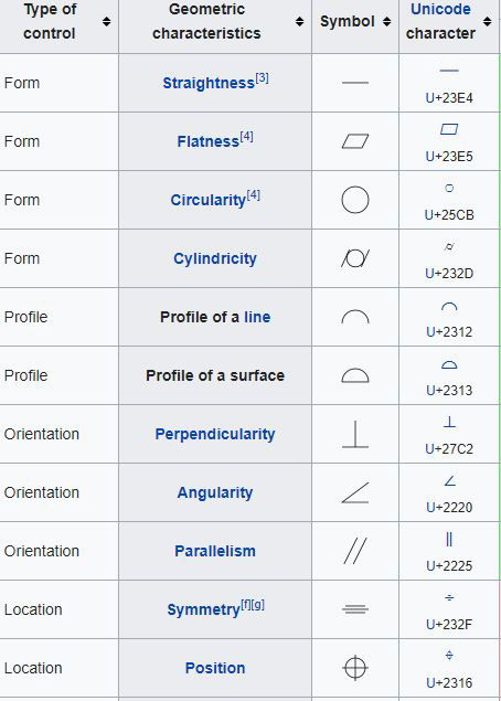
Geometric tolerancing reference chart (per ASME Y14.5 M-1982)
About the Author
Adebayo is a thought leader in continuous process improvement and manufacturing excellence. He is a Certified Six Sigma Master Black Belt (CSSMBB) Professional and Management Systems Lead Auditor (ISO 9001, 45001, ISO 22000/FSSC 22000 etc.) with strong experience leading various continuous improvement initiative in top manufacturing organizations.
You can reach him here.
