How to Tune a Controller On the Job (For Practicing Engineers and Students)
There is no engineering system on the planet today where controllers are not used. Controllers are everywhere. To successfully keep a controller in doing what it is supposed to do, controllers need to be tuned properly and hence the name 'Controller Tuning'. There are enough text books out there to tell you the theory and complex equations behind controller tuning and this is a topic that professors enjoy teaching in class (....And also an awesome subject for the provost to splash Red Ink all over Your Exam Paper to place you at the bottom of the grading list). Controller Tuning might look Cool on Your Resume But!! from a practical stand point in the industry, it becomes increasingly difficult to apply them in its raw form with a paper, pencil and calculator while on the job.
The following article is based on using a well known software tool called Aspentech HYSYS* that cuts down the mathematical headache to get your process facility to run the way you'd expect it to. A set of hand calculations is also included to understand how the controller is tuned.
 Click Here to Join the Over 3200 Students Taking our Highly Rated Courses on Quality Assurance/Quality Control, Project Management, Engineering, Food Safety, Lean Six Sigma, Industrial Safety (HSE), Lean Manufacturing, Six Sigma, ISO 9001, ISO 14001, ISO 22000, ISO 45001, FSSC 22000, Product Development etc. on UDEMY.
Design Procedure for Controller Tuning
A good controller is one that offers a suitable trade-off between performance and robustness and the standard type of controllers used even to this day are the proportional (P), proportional plus integral (PI), and the proportional plus integral and derivative (PID) controllers. To tune these controllers, 'Gain' (Kc), Integral Time' (Ti) and 'Derivative Time' (Td) are the three basic parameters needed and a procedure is required to estimate it. In this article, the procedure employed is called Internal Model Control (IMC).
Click Here to Join the Over 3200 Students Taking our Highly Rated Courses on Quality Assurance/Quality Control, Project Management, Engineering, Food Safety, Lean Six Sigma, Industrial Safety (HSE), Lean Manufacturing, Six Sigma, ISO 9001, ISO 14001, ISO 22000, ISO 45001, FSSC 22000, Product Development etc. on UDEMY.
What is Internal Model Control??
IMC refers to a systematic procedure for control system design based on the Q-parameterization concept that is the basis for many modern control techniques. What makes IMC particularly appealing is that it presents a methodology for designing Q-parameterized controllers that has both fundamental and practical appeal. As a consequence, IMC has been a popular design procedure in the process industries, particularly as a means for tuning single loop, PID-type controllers. The Author uses an example to demonstrate this.
Click Here to Join the Over 3200 Students Taking our Highly Rated Courses on Quality Assurance/Quality Control, Project Management, Engineering, Food Safety, Lean Six Sigma, Industrial Safety (HSE), Lean Manufacturing, Six Sigma, ISO 9001, ISO 14001, ISO 22000, ISO 45001, FSSC 22000, Product Development etc. on UDEMY.
Case Study
An inlet stream of 100 kgmol/hr at 5 barg containing 100 mol% methane passes through four valves. The pressure drop experienced at the 4 valves is 0.1 bar, 0.2 bar, 0.3 bar and 0.4 bar respectively to exit at a final pressure of 4 barg. VLV-100 has its hold-up volume of 2 m3 declared to take into account delay in the output flow variation. The minimum and maximum flow through valve VLV-100 is taken to be 0 kmol/h and 200 kmol/h respectively. The control valve (VLV-100) opening is modeled to transport 100 kmol/h at 50% opening. A closed loop, reverse acting flow controller (FIC-100) is added to VLV-100 & needs to be tuned as a P-I controller.
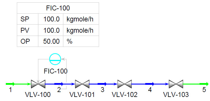

The purpose of the closed loop Flow controller (FIC-100) is to ensure that the flow through the control valve VLV-100 is always maintained at 100 kmol/h by adjusting the valve opening whenever the flow into it changes with time. Therefore the work to be done is to estimate what are the 'Kc' and 'Ti' values of the P-I controller that ensures a flow of 100 kmol/h is maintained by FIC-100 irrespective of the disturbances.
Click Here to Join the Over 3200 Students Taking our Highly Rated Courses on Quality Assurance/Quality Control, Project Management, Engineering, Food Safety, Lean Six Sigma, Industrial Safety (HSE), Lean Manufacturing, Six Sigma, ISO 9001, ISO 14001, ISO 22000, ISO 45001, FSSC 22000, Product Development etc. on UDEMY.
Basics of A PID Controller
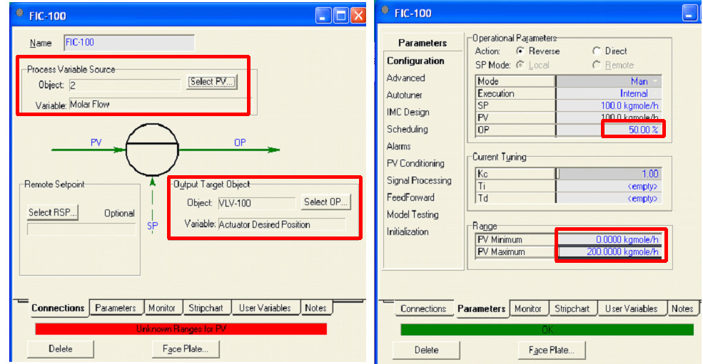
Before trying to model and tune a controller, understanding a few basic terms helps. A controller is defined by three parameters - Set Point (SP), Process Variable (PV) and Output (OP).
- Set Point (SP) - The parameter that you want to maintain. In this example, the flow rate of 100 kmol/h becomes the set point.
- Process Variable (PV) - The actual flow passing through the valve which can vary. In this example, PV becomes stream '2' through which the pressure driven flow can vary.
- Output (OP) - What the controller needs to change in order to ensure only 100 kmol/h of flow passes through the valve, VLV-100. In this example, OP is the valve opening that ranges between 0% to 100% opening.
- Proportional Control (P) - “How Far” the measured process variable (PV) has moved away from the desired set point (SP).
- Integral Control (I) - “How Long” the measured process variable (PV) has been away from the desired set point (SP).
Click Here to Join the Over 3200 Students Taking our Highly Rated Courses on Quality Assurance/Quality Control, Project Management, Engineering, Food Safety, Lean Six Sigma, Industrial Safety (HSE), Lean Manufacturing, Six Sigma, ISO 9001, ISO 14001, ISO 22000, ISO 45001, FSSC 22000, Product Development etc. on UDEMY.
- Derivative Control (D) - “How Fast” the error value changes at an instant in time.
- PV Min - Minimum Process Variable (PV Min) is the lowest amount of flow that can pass through the valve. In this case, the minimum flow is 0 kmol/h.
- PV Max - Maximum Process Variable (PV Max) is the highest amount of flow that can pass through the valve. In this case, for the sake of the exercise, the maximum flow is taken to be 200 kmol/h. Note: The maximum flow through a valve depends on the size of the valve and is represented by the term 'Cv'. Higher the Cv, larger is the valve and greater is the flow through the valve.
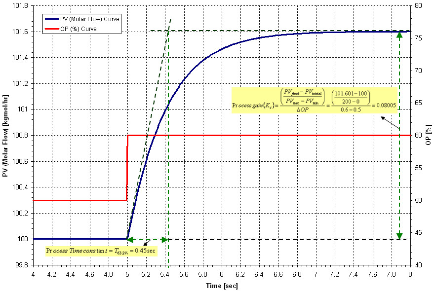
- Process Time Constant - This describes how fast a measured process variable responds when forced by a change in the controller output. The Process Time Constant is equal to the time it takes for the process to change to 63.2% of the total change in the measured process variable.
In the current case study, FIC-100 in the image is modeled as a P-I controller.
Click Here to Join the Over 3200 Students Taking our Highly Rated Courses on Quality Assurance/Quality Control, Project Management, Engineering, Food Safety, Lean Six Sigma, Industrial Safety (HSE), Lean Manufacturing, Six Sigma, ISO 9001, ISO 14001, ISO 22000, ISO 45001, FSSC 22000, Product Development etc. on UDEMY.
How is a Controller Tuned??
Do you remember how the circus ring master whipped the lash to train the Gorilla to moon walk?? Exactly the same way, a controller is tuned by causing a disturbance to the process and seeing how it reacts. Watching its reaction, the control parameters (Kc, Ti) can be adjusted to ensure the controller behaves like a trained gorilla in a circus.
In the current undertaking, the disturbance is introduced as - the valve (OP) which is at 50% opening for a flow rate of 100 kmol/h (PV) is momentarily changed manually to 60% opening (OP).
Upon doing so, the flow through the control valve, VLV-100(PV) is monitored as shown in the below figure.
Click Here to Join the Over 3200 Students Taking our Highly Rated Courses on Quality Assurance/Quality Control, Project Management, Engineering, Food Safety, Lean Six Sigma, Industrial Safety (HSE), Lean Manufacturing, Six Sigma, ISO 9001, ISO 14001, ISO 22000, ISO 45001, FSSC 22000, Product Development etc. on UDEMY.
To tune the controller using IMC design procedure, two steps are employed
- Estimate the value of Process Gain (Kp) and Process Time Constant [Tp] or T63.2%
- Estimate the value of Overall Gain (Kc) and Integral Time (Ti) i.e., P-I action.
From the above graph, Process gain (Kp) and T63.2% is calulated as,

Using the above values of Kp and T63.2%, the overall gain (Kc) and Integral Time (Ti) as a first order process with negligible dead time can be calculated as,

Using the calculated value of Kc=12.5 and Ti of 0.45 sec, the controller is programmed accordingly and executed to run.
Click Here to Join the Over 3200 Students Taking our Highly Rated Courses on Quality Assurance/Quality Control, Project Management, Engineering, Food Safety, Lean Six Sigma, Industrial Safety (HSE), Lean Manufacturing, Six Sigma, ISO 9001, ISO 14001, ISO 22000, ISO 45001, FSSC 22000, Product Development etc. on UDEMY.
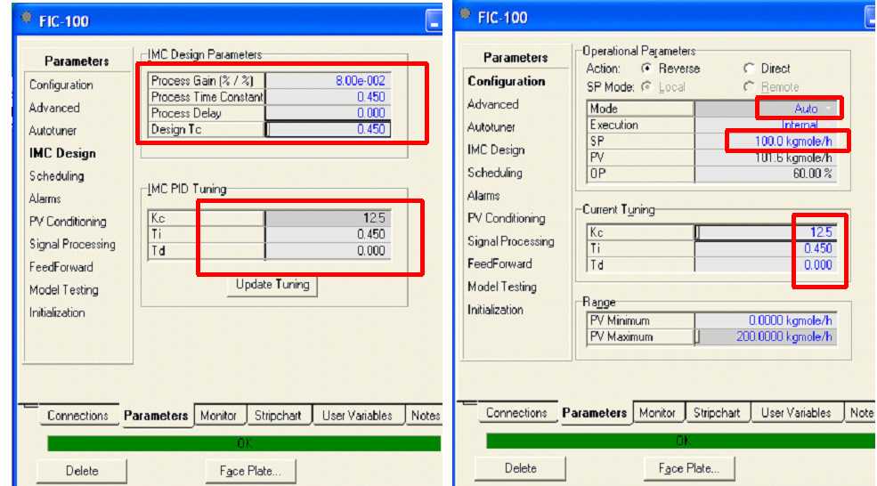
The response of the tuned P-I controller (FIC-100) when activated to run in automatic mode, i.e., when the controller is set to run on its own, gives us the result where the FIC-100 automatically adjusts the valve (VLV-100) % opening to ensure 100 kmol/h of flow passes through the system as follows.
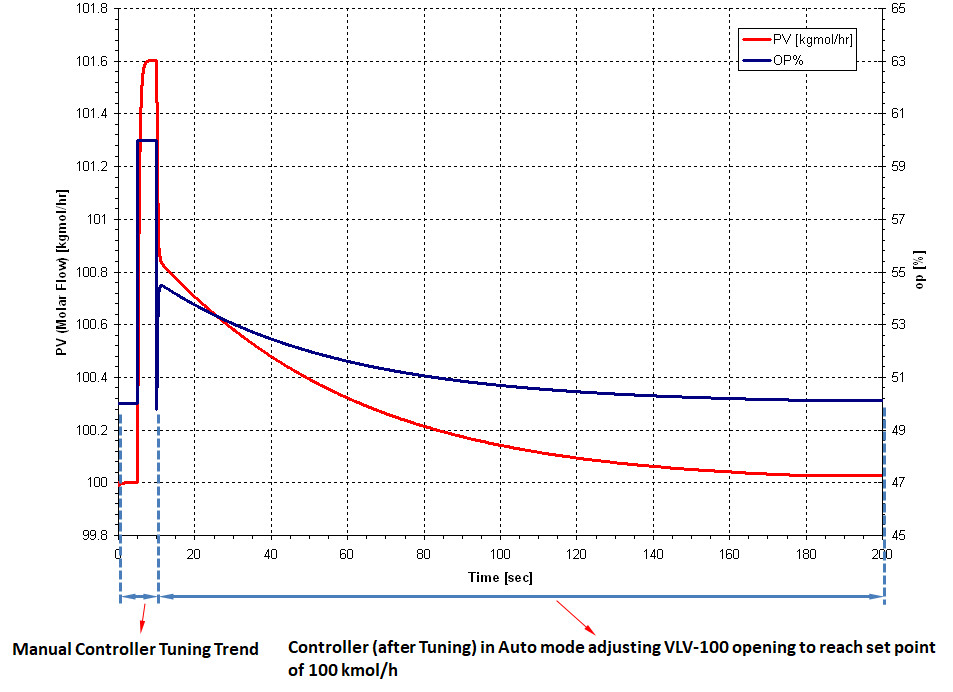
From the above graph, it is seen that the controller FIC-100, automatically runs to bring the valve to 50% opening with 100 kmol/h of flow passing through VLV-100 in about roughly 180 sec (~3 min). Using the tuned controller, with any changes hereafter in the incoming flow would mean, the flow controller (FIC-100) can automatically dictate by how much the control valve (VLV-100) has to open or close to ensure a flow of 100 kmol/h is maintained.
Click Here to Join the Over 3200 Students Taking our Highly Rated Courses on Quality Assurance/Quality Control, Project Management, Engineering, Food Safety, Lean Six Sigma, Industrial Safety (HSE), Lean Manufacturing, Six Sigma, ISO 9001, ISO 14001, ISO 22000, ISO 45001, FSSC 22000, Product Development etc. on UDEMY.
About the Author
Vijay Sarathy holds a Master’s Degree in Chemical Engineering from Birla Institute of Technology & Science (BITS), Pilani, India and is a Chartered Engineer from the Institution of Chemical Engineers, UK. His expertise over 16 years of professional experience covers Front End Engineering, Process Dynamic Simulation and Subsea/Onshore pipeline flow assurance in the Oil and Gas industry. Vijay has worked as an Upstream Process Engineer with major conglomerates of General Electric, ENI Saipem and Shell.
